
An Investigation into Methods to Assist Forced Water Landings for Conventional Aircraft - Making the ‘Miracle on the Hudson’ the Normal: A Feasibility Study
Date
March 2021 - August 2021
(6 Months)
Role
Individual Researcher
Project Type
Individual
Location
Cranfield University, Bedfordshire, UK

01
Introduction
There have been a significant number of investigations in the field of aircraft forced water landing (ditching), which includes analytical, numerical, and experimental investigations with a scaled aircraft model. Although previous studies have been able to reach positive conclusions in their own right, however, they do not have as broad application as recent studies, and their results are only valid in certain circumstances. In addition, there is inadequate and very limited research to have an idea for having ditching aid installed onto the existing aircraft.
-
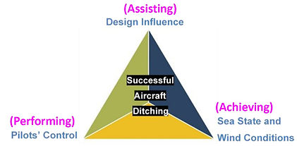
The key criteria that contribute to a successful aircraft ditching are design, pilot control, sea state, and wind conditions.
-
The project aim is to investigate the three significant aspects form the triangle of successful aircraft ditching interestingly in assisting, achieving, and performing the forced water landing.
-
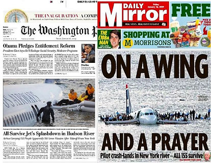
The idea of this feasibility study is to investigate into methods to assist forced water landings for conventional aircraft making the ‘Miracle on the Hudson’ the normal.
02
Literature Review
When an aircraft contacts water over an ocean, the hull sinks and is rarely recovered from the ocean floor. The reasons for a planned or unplanned impact on water can be very diverse:
-
Controlled Flight Into Terrain (CFIT),
-
technical failure/maintenance error,
-
crew incapacity (seldom in transport aircraft),
-
unknown.
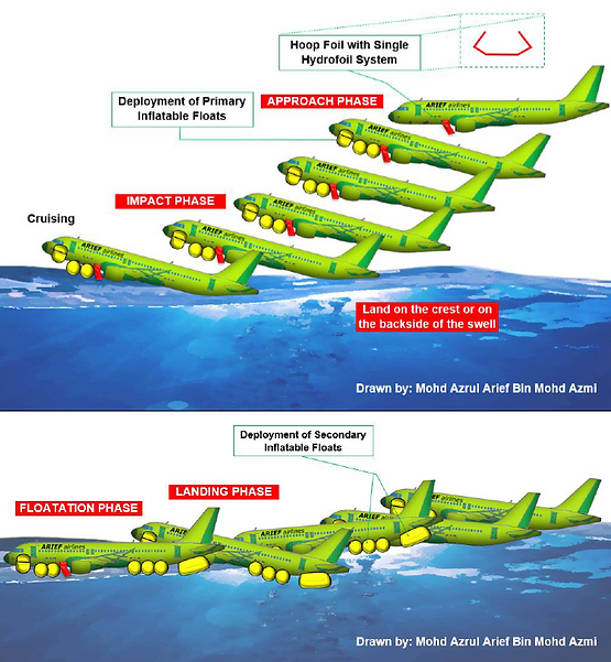
During an aircraft ditching, four different phases can be identified: approach, impact, landing, and floatation.
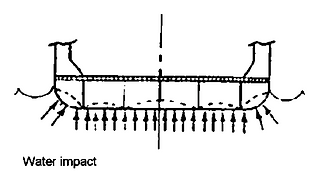
For a water impact, the level of structural damage is high. The impact forces are caused by the water pressure acting on the structure's outer surface. Impact loads are distributed along the skin panels, which must be transmitted to the water-absorbing structural components.
Due to the high forward velocity of an aeroplane ditching event, the following loads are applied to the aircraft structure:
-
The aircraft components are subjected to high hydrodynamic loads.
-
High drag forces acting on the landing gear bays, cargo doors, avionic hatch, and other opened fairings.
-
In the case of low wing engines, the loads resulting from the engines' potential rupture.
-
Loads caused by the potential loss of flaps.
-
Cavitation and ventilation effects at the fuselage lower shell cause a hydrodynamic effect.
-
The effects of aerodynamic forces on aircraft lighting surfaces
-
Suction effect
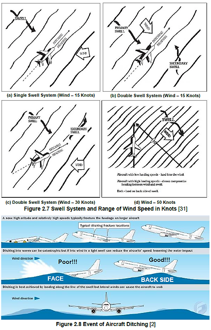
To choose a suitable ditching heading, the pilot must be aware of the sea and weather conditions. If an emergency occurs after darkness, the pilot should have a rough idea of the optimum ditching heading based on observations estimated during the day. As a result, pilots flying into dusk must take note of the sea conditions and decide on a ditching heading before darkness.
Dynamic buoyancy is consistent with the conservation of momentum, mass, and energy. Using energy from the engine is to push the air mass down and lift the aircraft, the air mass is pushed downward by the assistance of aircraft's wings. There is no net loss or gain of mass or energy. Hydrodynamic lift occurs when energy is transmitted from the partially submerged aircraft into the air.


03
Methodology
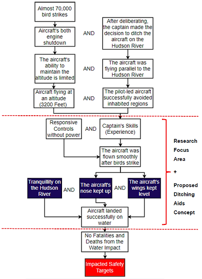
It was found that the flight 1549 incident had a positive impact on safety. The selected purple region in the figure (pilots’ control and water surface condition) will be discussed on next sections with new design ditching aids proposed.
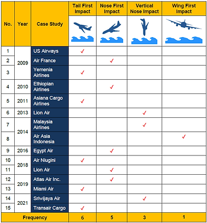
In order to design ditching aids onto existing aircraft, it is vital to study and develop accurately first ideas of which areas of the aircraft are likely to be damaged first from forced water landings using the prior case studies from 2009 to 2021. As a result, from the Table, it was stated that the most landing impact configurations occur when the aircraft is tail first and next is the nose. Thus, this study concentrates on the tail first impact.
The basic requirements for ditching aids ideas proposed shall:
-
The aircraft must have adequate buoyancy in required to address the maximum operational gross loading weight.
-
The goal is to keep assigned missions unaffected.
-
Compatibility with the aircraft's aerodynamics.
-
Compatibility with existing and/or proposed survival systems is required.
-
Compatibility with existing and/or proposed aircraft’s modification is required.
-
Minimize the amount of time crew members have to spend learning new requirements.
-
Maximize the current state of the art by giving the system maximum effectiveness.
-
Be capable of functioning on other aircraft types.
-
Preventive and corrective maintenance may be implemented using standard tools.
-
Represent production hardware as nearly as feasible.
Each of the ditching aids' initial ideas, as represented in Figure, will be examined in detail. Below are the areas of research on ditching aids:
-
An Emphasis on Ideas Proposed for Ditching Aids
-
Types of Selection Configurations, Shapes and Materials
-
The Methods on How and When the Ditching Aids Deployed
Example of Ditching Aids Ideas in Patent
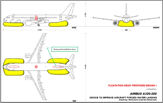
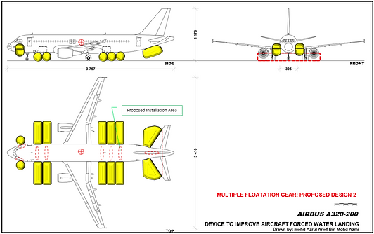
(1) Floatation Gear
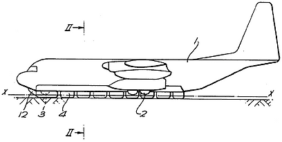
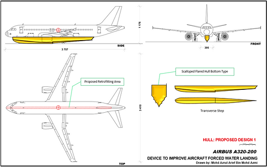
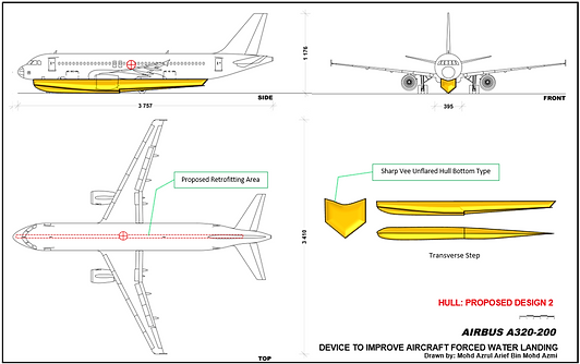
(2) Hull


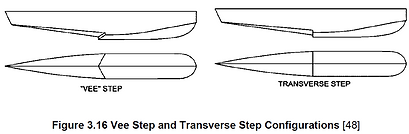
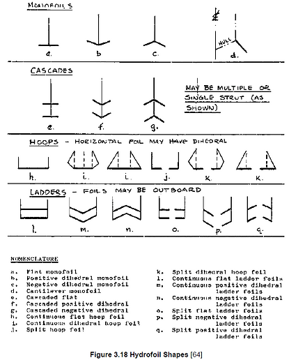
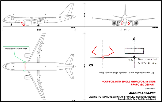
(3) Hydrofoils

(4) Hydroskis


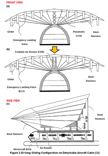
(5) Hang-Gliding
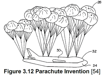
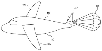
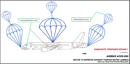
(6) Parachute
(7) Pyrotechnic Fastener / Explosive Bolt

04
Discussion of the Proposed Design Ideas Down-Selection and the Invention
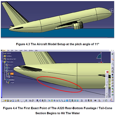
A plane of water surface formed to determine which exact point of the rear-bottom fuselage / tail-cone section contacts water. The aircraft model was oriented toward the water plane at the pitch angle of 11° as illustrates in Figure 4.3.
In Figure 4.4, the aircraft model has been zoomed in such that it can be determined where the first exact point begins to hit the water. Hence, the rear-bottom fuselage / tail-cone section is the first part that begins to hit the water. In the next section, the ditching aids are sketched out respectively.

Sketches of Proposed Layout Design


Pugh Matrix Design Selection
The Table tabulated the results of Pugh Selection Matrix on the Ditching Aids Proposed Designs including selection criteria. However, pyrotechnic fastener / explosive bolt of its application system designs is excluded from the selection since they are classed as explosive and hazardous materials, and their sole purpose is to disengage an aircraft part by melting or burning the bolts.


As seen in the Table above, hydrofoil design 1 (hoop foil with single hydrofoil system) scored the greatest overall weighted score.
Despite this design being the top option, the goal is to come up with the best possible solution to assist forced water landing for conventional aircraft by combining the other ditching aids as well to get a better concept. This combination method is to offset the negatives of the top option.
Based on the previous Table, the floatation gear design 2 and hull design 1 share the same total weighted score, which is 30. To evaluate both ditching aids, another down-selection has been made in Table beside and the top option will be the reference. To counteract the negative aspects of the top option, this alternative is implemented. It was therefore decided to incorporate the flotation gear design 2 with the hydrofoil design 1.
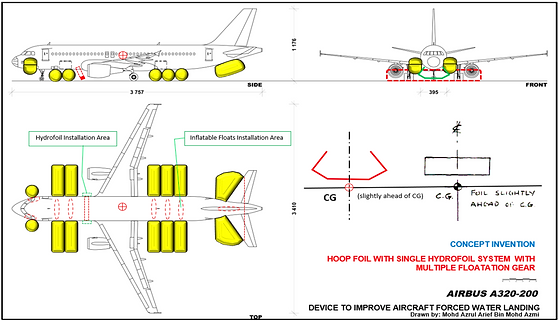
Figure beside depicts concept invention design after it was scrutinised with the use of the Pugh Selection Matrix. The hydrofoil is installed and mounted outboard of the aircraft fuselage in front of the belly, which slightly ahead of the CG. A large inflatable float is installed under the tail-cone section, 5 long inflatable floats are installed underneath the centre of the fuselage, and 2 vertical inflatable floats are installed at the side of aircraft nose.
The following are the reasons for this combination approach:
-
Lessen the loads exerted on the floats and associated fastener mechanism.
-
Less chance of primary floats being punctured by water surface because the presence of the secondary floats.
-
The aircraft's depth in the water during ditching can be reduced
-
The secondary floats might be spaced apart by a widespread, resulting greater stability.
-
The floats' freedom of movement is limited.
-
Increase floating stability by maximizing the transverse distance between two secondary floats.


05
Discussion on Sea and Wind Evaluation in Selecting Good Ditching Heading
Influence on Magnetic Ditching Heading Chart
In aviation, the terms "track" and "heading" are not equivalent. The track is the direct path the pilot intends to take from airport point A to point B on the Earth's surface.
For example, if the pilot wanted to fly north along this track under ideal conditions, the pilot would point the aircraft in the direction of his / her destination and fly the straight line across, but this is rarely achievable because your aircraft is constantly buffeted by wind and weather as illustrated in Figure 5.2.
Assuming that the wind is blowing from the Northeast. As the pilot fly, the wind constantly causes the aircraft to drift off track to the west as shown in Figure 5.2(a). The actual flight path the aircraft makes is called Track Made Good. The angle in between is called track error, and the consequence is some distance off track from the destination.
To prevent the track error, the pilot must point the error aircraft into the wind to compensate for the drift. The direction of the pilot will point the aircraft in is called the heading as shown in Figure 5.2(b) and (c). The pilot can observe the Magnetic Ditching Heading chart based to fly precisely along the planned track to the destination.
Based on the world region of Magnetic Ditching Heading chart from the USNO website that is available for public access dated on 1st September 2021, as illustrated in Figure 5.3, there are many headings line to guide the pilot to land on water during emergency landing at night.
Influence on Swell Wave Height
and Direction Chart
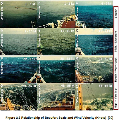
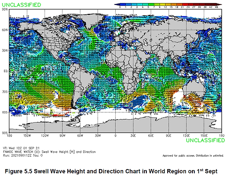
Figure 5.5 shows a chart of Swell Wave Height and Direction of the world region from the USNO website [84], dated on 1st September 2021. The colour gradients show the significant wave heights for swell. The black arrows show the wave direction.
From the colour bar index, the larger the feet (the redder), the higher the swell wave height. High swell wave height indicates the high speed (in knots) and dangerous for the pilot should land on water during emergency landing. In addition, the sea's shadow is darkened, and more whitecaps are occurred. The pilot should avoid this zone as it indicates rough waves. Conversely, the smaller the colour index (the bluer), the calmness the sea is.
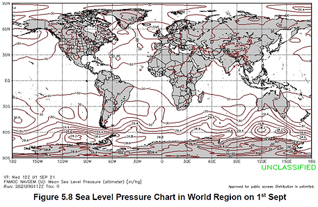
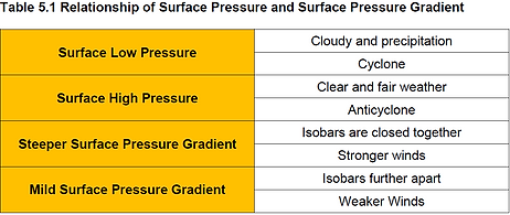
Influence on Sea Level Pressure Chart
There are many isobars (red lines) closed together at the south hemisphere especially in the region of Antarctica, which means stronger winds occurred at that region. Thus, create a steeper surface pressure gradient. Conversely, if the Isobars further apart, the weaker the wind will be.
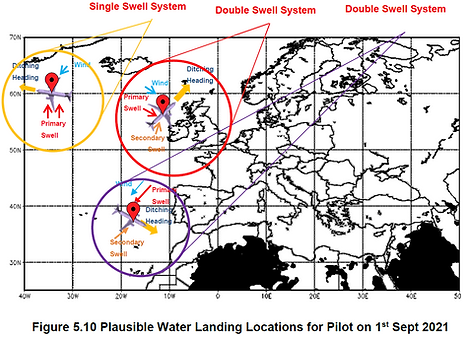
Summary of the Charts Analysis and Plausible Water Landing Locations
Figure 5.10 and 5.11 shows the summary of three plausible water landing locations including the ditching head direction, movement of wind and swell system classification. These results obtained from lines that intersect the best point of location for the pilot to land.

06
Discussion on Impact of Pilot Skills and Techniques on Flight Settings
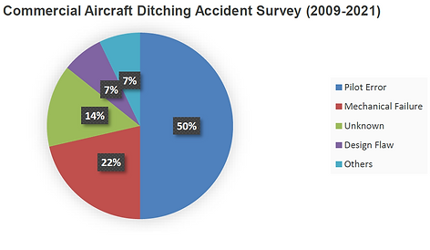
Figure demonstrates the basic statistics of the commercial aircraft ditching survey from 2009 until 2021. According to statistics, from 2009 to 2021, the leading cause of commercial aircraft ditching is pilot error, accounting for 50% of all incidents.
Influence on Flight Speed
Smooth deceleration is required so that it will less of a hazard to occupants. Low-speed landings are safer because impact forces and pressures are reduced. Attempt to avoid landing too fast or too slow.
If approach is too slow, and the airframe is stalled and pancaked in, results will not be good. Water can be as hard as concrete. Also, if the approach is too slow and rudder or elevator effectiveness is lost, it will risk roll and wing tip impact.
Too fast is equally deadly. Aircraft that develop at high speeds during landing will encounter longitudinal instabilities on water. A too fast approach means subjecting the airframe to unneeded and potentially catastrophic stresses. Fuselage and wing attach bolts and systems are obviously very strong. Strong enough to withstand years of turbulence and landing stresses. But water contact stress is immense.
Influence on Angle of Descent
Aircraft that make their landings at angles more than 5° have severe impact pressures that have been known to cause dives or, at lead to serious structural failures, and poor floatation time. The minimum gliding angle for most aircraft with the engine off is approximately 4°. If the pilot wants to lessen the angle of descent during touchdown, they can either 'flatten out' or use engine power to flatten the glide angle.
Influence on Attitude
A tail-well-down attitude will normally generate a reduced airspeed, but an attitude with the tail low and nose straight forward is optimal when it is highly likely that the aircraft will experience heavy impacts or suctions to the rear fuselage. If there is engine power, it is possible to get an almost-level attitude by using the entire flap and power set at their maximum settings.
Influence on Landing Gear Setting
When ditching, it is recommended that the landing gear be in the "up position" (retracted). Thus, by using this configuration, the aircraft will not nose-dive immediately after water hit because it will not have water rushing into its structure and it won't nose-landing directly down. As a result, diving is frequently caused by excessive gear. Contrary, extended gear usually causes diving.
If a ditching aid attached beneath the aircraft nose, tricycle landing gear provides structural members that are ideally considered to carry the concentrated load of the ditching aid.

Influence on Flap Setting
In almost all circumstances, reducing the speed reduces the risk of structural failures produced by impact loads on the fuselage.
Full extended flaps can cause the aircraft to pitch nose. Most flaps are strong enough to fail practically as soon as they hit the sea, thus the transient nose-down pitching moment has little effect when the maximum allowable flying speed with flaps down is less than 150 knots EAS (Equivalent Airspeed). The force required to break large-chord track flaps such Gouge or Fowler off is sometimes high and can last a long period. Split and slotted flaps are usually weaker. When they hit the sea, they tear apart causing no nose-down pitching moment.
Commercial aircraft use low wing. The split and slotted flaps can normally be lowered as much as needed; however, flaps of the Gouge or Fowler type should not be lowered. Following these guidelines, a pilot should select the flap setting that minimizes aircraft gliding angle, unless the pilot has engine power available to flatten the aircraft glide path, or if the pilot expects to have enough time to flatten out the aircraft glide path before touchdown.
Influence on Engine Power Setting
Additional power should be utilised after the aircraft has slowed down to 10 knots or so above stall, to overcome the higher drag generated by the nose-up attitude. When a smooth stretch of water appears ahead, reduce power and touchdown as fully stalled as possible at the optimum recommended speed. Cutting power when approaching a smooth area prevents overshooting and reduces the likelihood of a second uncontrolled landing. It is recommended to always have extra power to maintain a nose-up attitude of 9° to 12 and 10 to 20% over stall speed until contact is made with the water.
If only one side of the power is operational, a small amount of power should be used to flatten the approach, but not so much that the aircraft cannot be turned against the good engines all the way down to the stall with a margin of rudder movement available. When near the stall, excessive imbalanced power can cause directional control loss. If only one side has power, a faster glide approach speed should be used. This will ensure good control and speed after levelling off without overpowering the power.
07
Conclusions
The general conclusion can be summarized as follows:
-
Pilot error is the leading cause of commercial aircraft ditching, accounting for 50% of all incidents from 2009 to 2021. Making decisions in the midst of stressful events including dealing with frightened passengers and dealing with turbulence, is significantly more challenging to make a rational decision.
-
In accordance with the accident investigation of the "Miracle on the Hudson", the rear-bottom fuselage / tail-cone section was the first part of the aircraft to come into contact with the water. During the event, the fuselage pitch angle was 11°. It was discovered that the incident involving flight 1549 had a favourable impact on safety.
-
Investigating methods in making the forced water landing as the ‘Miracle on the Hudson’ the normal were achieved by:
-
Design in assisting the ditching
-
Pilot’s control in performing the ditching
-
Sea state and wind conditions in achieving the ditching
-
-
One of the goals of this work was to showcase the proposed design idea and adequate documentation has been presented to enable the invention to proceed. Minor changes to airworthiness or environmental parameters like mass, balance, structural strength, and reliability have "NO appreciable effect".
-
The Pugh Selection Matrix refined the current ideas. Each idea has its own advantages and disadvantages, thus there was rarely a single notion that is better than the others. The Pugh Matrix improved concepts by removing undesired attributes and only incorporating positive ones.